|
The simplest configuration of a capacitive position sensor is two close-spaced parallel plates. The capacitance of the sensor
is proportional to the area of the electrodes and the dielectric constant, and inversely related to the space between
the parallel plates. Therefore, capacitive sensors can be used for direct measurements of motion/distance, chemical composition
and electrical field, and for indirect measurements of other variables which can be converted into motion, dielectric constant,
such as presure, acceleration, fluid level and composition etc.
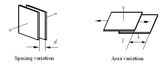
Fig. 1 Capacitive position/displacement sensors with two variations
Spacing and area variations (Fig. 1) are often used for noncontact measurements of angle, linear displacement, and sub-mircon
plate spacing. The spacing variation of parallel plates is suitable for motion detection if the spacing change is less than the
electrode size. The capacitance is inversely related to the space in this case. When displacement increases to the demension of
the electrodes, measurement accuracy of the spacing variation suffers from vanishing signal level. The area variation is then preferred.
As the plates slide transversely, the capacitance of the area variation changes linearly with motion. Using an Impedance-Voltage Converter
(Fig. 2), the capacitance change can be converted into a voltage change for further signal processing.
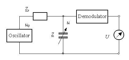
Fig.2 Impedance-Voltage converter working nearby resonance frequency
Capacitive sensors should be excited by a high-oscillation frequency nearby the resonance frequency of the circuit so that electrode impedance is
as low as possible and the sensitivity to displacement reaches the maximum. The resonance frequency of an impedance-voltage converter for
capacitance sensors depends on the geometric sensor parameters and the serial impedance Zs. The serial impedance
must be high enough in order to obtain a high sensitivity. The resonance frequency is determined by measuring the maximum output signal
under using a maximum space. After demodulation of the output voltage u one obtains the
output voltage U as function of the distance d or l. Fig. 3 shows the output signal at different excitation frequencies.
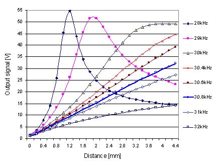
Fig. 3 Response voltage of a capacitive displacement sensor nearby its resonance frequency 30.4kHz
using spacing variation
Capacitive sensor performance is related to the change in sensor capacitance/impedance over the calibrated range of target/plate motion.
The measuring range increases with the excitation frequency, while the sensor sensitivity decreases with the excitation frequency.
At the resonance frequency, for instance, the output voltage changes from 6.0V/mm to 12V/mm in a measuring range of 4mm.
The output voltage changes from 21V/mm to 97.0V/mm at the frequency 28kHz for a small measuring range of 1mm . Therefore,
capacitive sensors have a very high sensitivity. A resolution of 0.5nm for motion detection is realizable using a excitiation
frequency near the resonance frequency.
In order to increase the measuring range and improve the linearity of a capacitive sensor, the excitation frequency and signal processing circuits
must be optimized. The optimal excitation frequency for the example sensor is 30.8kHz. In this case the sensor sensitivity varies from 7.1 to 7.2 and
is more constant in a measuring range of 4mm. A linearity of 0.05% is realizable by optimizing the excitation frequency,
sensor structure and signal processing circuits.
Special sensor electronics, signal processing and self-calibration are developed for compensating
temperature and other influences. Thus, the developed capacitive sensors can be applied to the positioning of photolithography
and the wafer-positioning in the semiconductor technology. They find a lot of applications to the measurements of position/distance, vibration, acceleration,
pressure, liquid level etc. in control engineering.
|